Programming GPIO Interrupts with Embedded Rust
2019-03-17Why interrupts?
Polling a GPIO to read the state of a button is simple enough to implement but suffers from a number of problems:
- Your program will need to ensure it's still scanning for button presses at regular intervals when performing other tasks.
- It is not energy efficient to have the processor scanning for button presses all the time.
- You cannot take advantage of processor sleep modes available to conserve energy when your program is not busy.
The better alternative is to instead make use of a hardware interrupt.
With an interrupt-driven interface, a button press will trigger a hardware interrupt on the processor. The processor will complete the current instruction and then jump to a predefined function which serves as our "interrupt handler".
In this article you will learn how to connect a hardware interrupt handler to the built-in user button on the STM32F3DISCOVERY board.
What do you need to know?
In order to implement an interrupt-driven interface you will need to know:
- The mapping between the processor and the Discovery's user button
- How to set the processor up to handle an interrupt
- How to define a function to serve as our interrupt handler
- How to safely access shared resources from our main program loop and interrupt handler
We'll be using the stm32f303 Peripheral Access Crate (PAC) as our primary interface to the board.
Links:
- The Embedded Rust Book: Chapter 6, Concurrency
svd2rustPeripheral API documentationstm32f303PAC documentation- STM32F3Discovery User Manual (pdf)
- Page 18, 6.4 and 6.5: Hardware layout and configuration for LEDs and Push-buttons
- STM32F303VCT6 Reference Manual (pdf)
- Page 292, Chapter 14.2: Extended interrupts and events controller (EXTI)
Mapping the hardware connections and peripherals
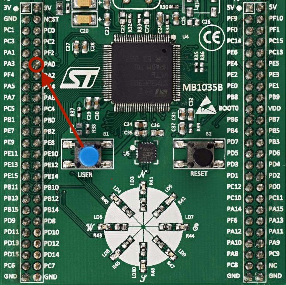
Button B1 USER on the Discovery is connected to pin PA0 on the STM32F303VCT6 which corresponds to pin 0 on the GPIOA (General-purpose I/O 'A') peripheral:
You will also be working with the EXTI (Extended interrupts and events controller) and NVIC (Nested vectored interrupt controller) peripherals.
Rust API's for these are exposed by the following crates:
| Crate | Peripheral API |
|---|---|
stm32f30x | GPIOA |
stm32f30x | SYSCFG |
stm32f30x | EXTI0 |
cortex_m | NVIC |
The peripheral wrappers provided by these crates are singletons and can only be obtained through the Peripherals::take method.
Calling the method the first time returns an Option containing the instance. Subsequent calls will return a value of None:
...
use cortex_m;
use cortex_m_rt::entry;
use stm32f30x;


#[cortex_m_rt::entry]
fn main() -> ! {
    let cortexm_peripherals = cortex_m::Peripherals::take().unwrap();
    let stm32f3_peripherals = stm32f30x::Peripherals::take().unwrap();
    ...
Implementation
This article demonstrates how to use the Discovery's user button to trigger hardware interrupts but you will find that most other peripherals or processor functions follow a similiar pattern:
- RCC Peripheral: Enable GPIOA and SYSCFG clocks
- GPIOA: Configure PA0 pin as an input in pull-down mode
- SYSCFG: Connect EXTI0 line to PA0 pin
- EXTI: Configure EXTI0 line
- Move shared peripherals into mutexes
- NVIC: Enable EXTI0 interrupt line and enter main loop
- Handle interrupt and clear the EXTI0 line 0 pending bit
1. RCC: Enable GPIOA and SYSCFG clocks
To save power, the default state of the GPIOA (General-purpose I/O) and SYSCFG (System configuration controller) peripherals are powered-down.
In order to power them up you will need to use the RCC (Reset and clock control) peripheral to enable their clock signals.
The GPIOA clock is controlled by the RCC_AHBENR register (RCC advanced high-performance bus peripheral clock enable register):
-
9.4.6:
AHB peripheral clock enable register (RCC_AHBENR)
Click to show
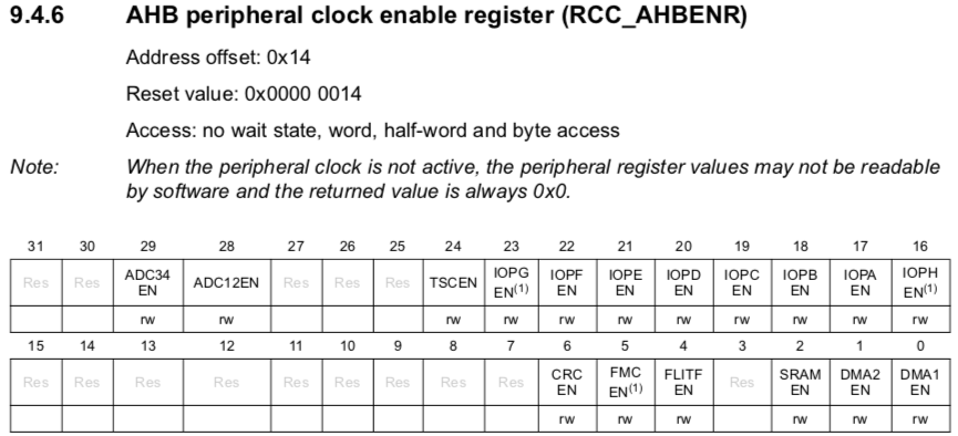
let rcc = &stm32f3_peripherals.RCC;
rcc.ahbenr.modify(|_, w|  w.iopaen().set_bit());   // enable clock for GPIOA
The SYSCFG clock is controlled by the RCC_APB2ENR register (RCC advanced peripherals bus peripheral clock enable register):
-
9.4.7:
APB2 peripheral clock enable register (RCC_APB2ENR)
Click to show
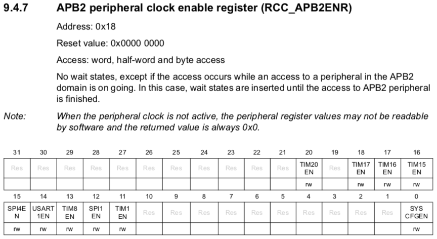
rcc.apb2enr.modify(|_, w| w.syscfgen().set_bit()); // enable clock for SYSCFG
2. GPIOA: Configure GPIOA to set PA0 pin as an input in pull-down mode
Once we have powered up GPIOA we will need to configure the PA0 pin as an input.
This is done by setting GPIOx_MODER register (GPIO port mode register) of the GPIOA register block:
-
11.4.1:
GPIO port mode register (GPIOx_MODER)
Click to show
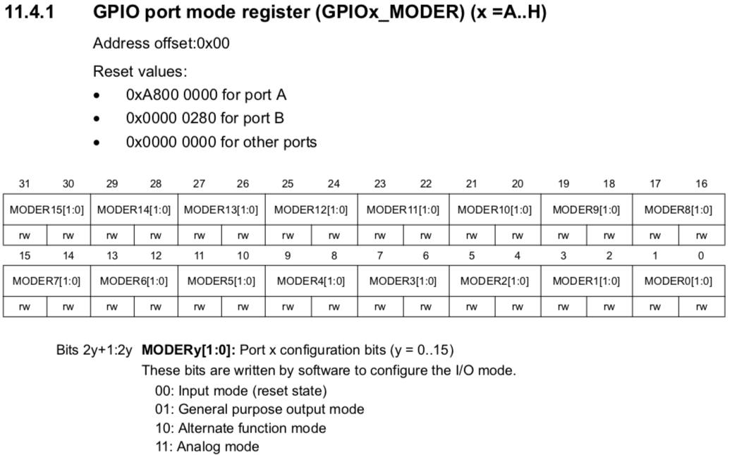
let gpioa = &stm32f3_peripherals.GPIOA;
gpioa.moder.modify(|_, w| w.moder0().input()); // moder0 corresponds to pin 0 on GPIOA
To configure the pin to operate in pull-down mode you need to set the gpio_PUPDR (GPIO port pull-up/pull-down register):
-
11.4.4:
GPIO port pull-up/pull-down register (GPIOx_PUPDR)
Click to show
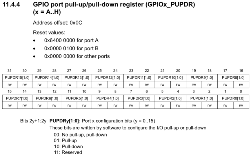
gpioa.pupdr.modify(|_, w| unsafe { w.pupdr0().bits(0b10) }); // set mode to pull-down
3. SYSCFG: Connect EXTI0 line to PA0 pin
The STM32F303VCT6 processor provides a number of EXTI controllers that can be configured to generate interrupts in response to events on the processor pins.
We want to generate an interrupt on the EXTI0 line in response to pin PA0.
To do this you need to configure the SYSCFG_EXTICR1 register as follows:
-
12.1.3:
SYSCFG external interrupt config register 1 (SYSCFG_EXTICR1)
Click to show
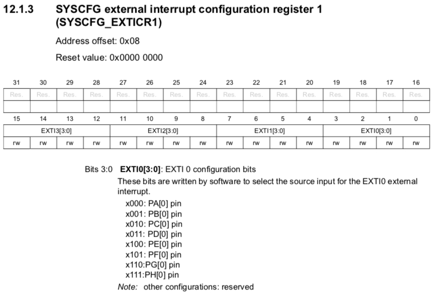
let syscfg = &stm32f3_peripherals.SYSCFG;
syscfg.exticr1.modify(|_, w| unsafe { w.exti0().bits(0b000) }); // connect EXTI0 to PA0 pin
4. EXTI: Configure EXTI0 line
To configure the EXTI0 line you will need to unmask the interrupt and set it up to trigger on the rising-edge of the signal coming in on pin PA0.
Unmasking the interrupt is done by setting the appropriate bit on the EXTI_IMR1 register (EXTI interrupt mask register):
-
14.3.2:
Event mask register (EXTI_EMR1)
Click to show
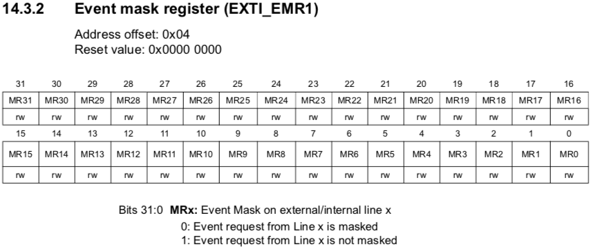
let exti = &stm32f3_peripherals.EXTI;
exti.imr1.modify(|_, w| w.mr0().set_bit());   // unmask interrupt
To configure the trigger behaviour you need to use the EXTI_RTSR1 register (EXTI Rising trigger selection register):
-
14.3.3:
Rising trigger selection register (EXTI_RTSR1)
Click to show
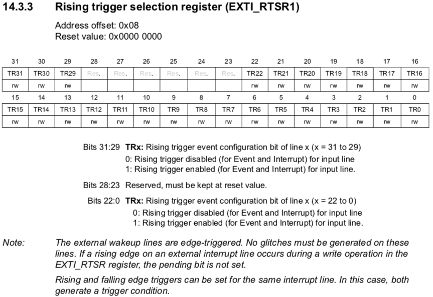
exti.rtsr1.modify(|_, w| w.tr0().set_bit()); // trigger on rising-edge
5. Move shared state into mutexes
When our interrupt is triggered the processor will stop whatever it is doing and jump to our interrupt handler function.
In this function we will need to access the EXTI peripheral and clear the pending bit for line 0. If we do not do this, the interrupt will continue to be triggered.
This means we will need to make our EXTI peripheral available globally to both the main() function and the EXTI0() interrupt handler function.
One problem with globally shared state is that it can easily result in a race condition.
Race conditions occur when an update on a resource in one part of the program is interrupted before completion by another part of the program modifying the same resource.
Fortunately Embedded Rust provides several synchronisation primitives which allow us to ensure exclusive access to a resource.
For this article we will be wrapping our globally shared resources in a Mutex.
First you will need to declare and initialize new global instances for each shared peripheral:
...
#[macro_use]
extern crate lazy_static;

use core::cell::RefCell;
use cortex_m::interrupt::Mutex;

lazy_static! {
    static ref MUTEX_GPIOA: Mutex<RefCell<Option<stm32f30x::GPIOA>>> = Mutex::new(RefCell::new(None));
    static ref MUTEX_EXTI:  Mutex<RefCell<Option<stm32f30x::EXTI>>>  = Mutex::new(RefCell::new(None));
}

#[cortex_m_rt::entry]
fn main() -> ! {
...
Then, before you actually enable the EXTI0 interrupt, you need to move the GPIOA and EXTI peripherals into the Mutex:
cortex_m::interrupt::free(|cs| {
    MUTEX_GPIOA.borrow(cs).replace(Some(stm32f3_peripherals.GPIOA));
    MUTEX_EXTI.borrow(cs).replace(Some(stm32f3_peripherals.EXTI))
});
After doing this, any attempts to access them without first wrapping them inside a critical section will result in a compilation error.
6. NVIC: Enable EXTI0 interrupt line and enter main loop
Finally you can enable interrupts on the EXTI0 line and enter the main loop:
let mut nvic = cortexm_peripherals.NVIC;
nvic.enable(stm32f30x::Interrupt::EXTI0);

loop {
}
Our program will now loop infinitely until a button press triggers an interrupt and the processor invokes our interrupt handler.
7. Handle interrupt and clear the EXTI0 line 0 pending bit
To handle our interrupt the processor needs to know the address of the function it should jump to whenever the interrupt is triggered.
Embedded Rust provides an #[interrupt] function attribute you can use to easily define interrupt handlers and associate them with their corresponding interrupt line.
The syntax consists of adding the attribute and then naming the function according to the interrupt line it is to be assigned to:
use stm32f30x::interrupt;

#[interrupt]
fn EXTI0() {
    ...
}
You can now handle the interrupt by first clearing the EXTI0 line 0 pending bit to prevent the interrupt from being triggered again once the function has completed:
#[interrupt]
fn EXTI0() {
    interrupt::free(|cs| {                             // enter critical section
        let exti = MUTEX_EXTI.borrow(cs).borrow();     // acquire Mutex
        exti.as_ref().unwrap()                         // unwrap RefCell
            .pr1.modify(|_, w| w.pr0().set_bit());     // clear the EXTI line 0 pending bit
    });

    let button_state = interrupt::free(|cs| {          // enter critical section
        let gpioa = MUTEX_GPIOA.borrow(cs).borrow();   // acquire Mutex
        gpioa.as_ref().unwrap()                        // unwrap RefCell
             .idr.read().idr0().bit_is_set()           // read and return button state
    });

    // do something with button_state
}
Conclusion
Interrupts are a complex topic but also intrinsic to embedded programming.
Without a solid understanding of interrupts many intermediate and advanced topics in embedded programming remain a closed door.
Whether you are learning about preemptive multitasking, DMA, timers, ADC/DAC interfaces or audio codecs the very first thing you will run into is the need to understand how each of them uses interrupts.
I hope this article has helped you to acquire some of the basic knowledge required to no longer be scared of them!
A note about safety
The astute reader may have noticed a number of instances in the article where I'm using unsafe code.
The reason for this is that I implemented the code using a PAC (Peripheral Access Crate).
At this level of abstraction the compiler cannot enforce consistency between the configuration of registers and the operations being performed on them.
For this reason the PAC API's have been designed to require explicit marking of areas of code that cannot be type-checked for consistency with the rest of my program.
In another article I will look at how Embedded Rust can help us avoid this issue by using a HAL (Hardware Abstraction Layer) crate.
More information:
- Pramode C.E - Programming an ARM microcontroller in Rust at four different levels of abstraction (sources)
- The Embedded Rust Book Chapter 4.1: Typestate Programming
Source code
You can find the code for this article in the github repo:
git clone https://github.com/antoinevg/stm32f3-rust-examples.git
cd stm32f3-rust-examples
make deps

# run in one terminal
openocd -f openocd.cfg

# run in another terminal
cargo run --bin stm32f3-01-interrupts